Power Budget for a Mobile Robot
Calculating continuous versus peak current draw, preventing inductive motor voltage sag from rebooting onboard computers, and properly selecting battery chemistries.
1. Why Capacity (Ah) is Only Half the Story
A common beginner pitfall in autonomous mobile robots is selecting a battery based solely on Amp-hour (Ah) capacity. A battery's ability to sustain mobile robotics depends equally on three electrical parameters:
- Nominal Voltage & Chemistry: LiFePO4 (lithium iron phosphate) offers exceptionally flat discharge curves (3.2V/cell nominal) and thermal safety, while Li-ion (NMC) provides higher gravimetric energy density at the cost of steep voltage degradation over discharge.
- C-Rate (Discharge Capability): A 10 Ah battery rated at 1C can only deliver 10A continuously. If four brushless drive motors demand 28A during rapid obstacle avoidance acceleration, the battery enters severe overcurrent, triggering the Battery Management System (BMS) cutoff.
- Internal Resistance & Voltage Sag: Under peak current
I_peak, internal cell resistanceR_icauses instant voltage drops:ΔV = I_peak × R_i. A 24V pack sagging down to 18V under motor acceleration instantly trips undervoltage lockouts on sensitive onboard electronics.
2. Separating High-Current and Clean Logic Rails
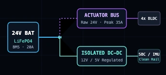
DC motors act as both inductive loads and generators. Rapid acceleration causes massive current spikes, while abrupt braking induces high-voltage back-EMF spikes that travel down power traces. If an embedded computer (NVIDIA Jetson, Raspberry Pi) shares an unfiltered power wire with motor ESCs, brownouts and spontaneous reboots will occur.
# Typical DC-DC Power Distribution Architecture
[ 24V LiFePO4 Battery Pack (8S / 25.6V nominal) ]
     │
     ├──[ 40A Main Fuse ]──[ E-Stop Switch ]
     │        │
     │        ├── (Raw 24V High-Current Rail) ──> [ 4x BLDC Motor Controllers ]
     │
     └──[ High-Frequency LC Low-Pass Filter ]
              │
              ├──> [ Isolated 24V-to-12V Buck Converter (10A) ] ──> Jetson SBC / LiDAR
              └──> [ Isolated 24V-to-5V Buck Converter (5A) ]   ──> IMU / Microcontroller
3. Continuous vs Peak Current Sizing
A realistic power budget distinguishes baseline idle from transient dynamic maneuvering:
- Continuous Logic & Sensing: Edge computer (15W) + 3D LiDAR (10W) + Stereo Camera (3W) + Routers/IMU (4W) = 32W (~1.3A at 24V continuous).
- Continuous Driving: 4x hub motors cruising at 1.0 m/s on level floor = 48W (~2.0A at 24V).
- Peak Acceleration & Stall: Overcoming obstacles, carpet friction, or ramp inclines can temporarily pull 8A to 10A per wheel motor (35A+ aggregate surge for 1–3 seconds).
Power Rule of Thumb: Always size the battery continuous discharge rating to at least 1.5× the total maximum continuous load, and verify that the BMS pulse discharge rating accommodates 1.3× the simultaneous stall current of all drive actuators.
4. Common Practical Mistakes
- Undersized Wiring & Ground Bounce: Using thin wiring between battery and motors creates resistive voltage drops. High motor return currents passing through a shared ground wire shift the reference voltage of digital sensors, causing I2C and UART bus errors. Always use a single star-ground configuration.
- Neglecting DC-DC Converter Efficiency: Switching regulators typically achieve 88%–94% efficiency. Running converters at their maximum thermal limit without heat sinking induces thermal shutdown during hot ambient operation.
- Relying on Generic USB Power Banks: Consumer power banks frequently shut down unexpectedly when load changes rapidly or when low-draw sleep modes make the power bank assume no device is attached.
- No Dedicated Emergency Stop: An electrical E-stop should physically disconnect actuator power through an automotive relay or contactor while leaving the compute and telemetry rail intact to record error logs.