LiDAR & IMU Basics
Range measurements describe the world around a robot. Inertial measurements describe its motion. Their strengths are different, which is why they are often used together.
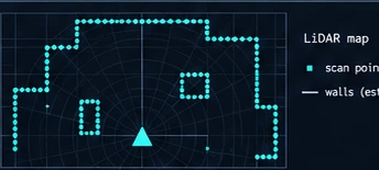
What each sensor measures
A time-of-flight LiDAR estimates distance from the travel time of a light pulse. A simplified relation is R = c Δt / 2: the measured time includes the outward and return journey. Scanning the beam produces a set of range measurements, often represented as a point cloud. Not every LiDAR uses this exact measurement method, and range, scan rate and field of view vary by device.
An inertial measurement unit commonly contains accelerometers and gyroscopes. A gyroscope measures angular velocity. An accelerometer measures specific force, rather than position; estimating motion requires careful treatment of gravity, bias and orientation. An IMU can update between LiDAR scans, but integrating noisy measurements accumulates error.
Why combining them helps
LiDAR scan matching compares observations of the surrounding geometry to estimate movement. It needs useful structure: a long featureless corridor, moving objects or poor returns can weaken the estimate. An IMU supplies short-term motion information even when an external scene is temporarily ambiguous. It does not provide an independent absolute position fix.
A fusion system combines measurements with a motion model and an estimate of uncertainty. The result is not automatically correct simply because two sensors are present. A poorly calibrated or badly timestamped sensor can make an estimate worse.
A practical integration sequence
- Inspect each sensor independently. Check units, coordinate axes, timestamps and whether the data rate is stable.
- Define the rigid transform between sensors. A mounting offset affects the interpretation of rotation and translation.
- Check time alignment while the platform moves. A static scene alone can hide synchronization errors.
- Introduce one measurement source at a time and compare the estimate against a repeatable reference.
For example, record a slow straight-line movement followed by a turn and a return to the start. Look for discontinuities, inconsistent headings and growing drift. This is an illustrative exercise, not a specified accuracy test.
Common practical mistakes
- Unsynchronized timestamps: Even 20 ms of clock divergence between LiDAR sweeps and high-rate IMU packets distorts point clouds during rotational maneuvers. Use hardware PTP or PPS synchronization.
- Ignoring chassis vibration: Motor and gearbox harmonics couple directly into MEMS accelerometer axes, generating artificial integration drift. Use mechanical damping grommets and low-pass digital filtering.
- Coordinate frame (TF) sign errors: Inverting a single rotation axis (such as Roll or Pitch) corrupts the gravity compensation vector, causing the EKF covariance matrix to diverge rapidly.
- Relying solely on visual RViz confirmation: A visually appealing map does not guarantee metric loop-closure accuracy. Always validate with measurable physical ground truth targets.
Limits to remember. Reflective surfaces, vibration, moving scenes and changing bias can affect measurements. A high update rate is not an accuracy specification. Evaluate the complete system under the conditions in which it will operate.