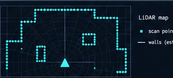
Sensors & perception
LiDAR & IMU Basics
Understand range scans, inertial measurements and the practical limits of combining them.
Read noteA small collection of reference guides, illustrative designs and tools for curious engineers.
Explore the notes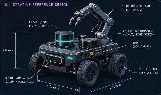
Short, practical introductions.
Start with a question, then follow the references.
Understand range scans, inertial measurements and the practical limits of combining them.
Read note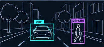
Follow a camera frame from capture to inference, and learn what to measure before optimizing.
Read note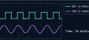
Explore scheduling latency, PREEMPT_RT and why a fast benchmark is not a timing guarantee.
Read note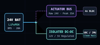
Continuous versus peak current draw, preventing inductive motor sag, and DC-DC rail isolation.
Read noteA reference architecture connects sensing, estimation and control. The illustration is a concept; real components must be selected against measured requirements.
Explore the sensing layer →First-principles engineering estimators.
Understand assumptions before selecting actuators.
Explore the gravity torque of a point payload on a massless arm. Angle is measured above horizontal.
τ = m × 9.80665 × L × cos(θ), where m is mass in kg and L is distance to the payload in metres. θ is measured from horizontal.
This static estimate excludes arm mass, acceleration, friction, transmission losses, structural limits and safety factors. It is not a six-axis simulation or a component-selection tool. Educational use only; not for safety-critical design.
Estimate theoretical linear rover speed from motor RPM, gearbox reduction and tire diameter.
v = (π × D × (RPM / G)) / 60, where D is diameter in metres, RPM is motor speed, and G is the reduction ratio.
Assumes rigid non-deforming tires, zero wheel slip, and perfect traction. Does not account for motor torque curve drop-off under load, terrain slope resistance, or rolling friction.
Practical checklists, offline references, and documentation directories designed for fast access in the workshop or terminal.
CKW Robotics Lab is a small collection of independent educational notes about robotics and embedded computing. “Lab” describes the exploratory format, not a claim of a physical research facility. Diagrams and platform designs are illustrative; examples are not published hardware benchmarks.